Optimal design of container in extended container movable house (1)
Abstract: the finite element analysis software is used to analyze and calculate the stress and displacement of the container in the improved extended container movable house under various loading and unloading conditions. At the same time, the size optimization design of the main stressed components of the container is carried out by using the idea of optimization design. Under the same working conditions, the results of optimal design are compared with those before optimization. After the optimized design, the self weight of the box is reduced by 15%, the maximum stress of the box is reduced from 162mpa to 126mpa, and the position of the maximum stress is also changed; The maximum deformation increases from 8181mm to 1219mm, and the positions are in the center area of the bottom short beam and the auxiliary long beam; The stress and deflection of the main stressed member - the long beam at the bottom are reduced.Key words: container finite element analysis stress displacement optimization design
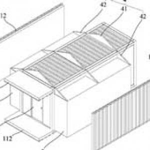
The container in the extended container movable room is reformed on the basis of standard container. The corrugated board on the side of the standard container is replaced by a foldable coaming. The coaming is hinged with the coaming and between the coaming and the container column. The coaming can be pulled out through the foundation beams on both sides of the box to form an extended structure. In addition, the roof truss and roof panel can form an extended container movable room (as shown in Figure 1).

Fig. 1 elevation of expansion container type movable house
Since the storage and transportation part of the movable room is made of standard containers (6058mm in shape) × 2438mm × 2438 mm) is formed by removing the corrugated plates on both sides, then the mechanical properties of this container will be reduced. After preliminary calculation and loading of house facilities (total weight 80KN), the container can not meet the requirements of various loading and unloading conditions. Therefore, after analysis and checking calculation, the following improvement schemes are put forward for the box (see Figure 2 for the improved shape): 1) add an auxiliary long beam on the bottom of the container; 2) Add tie rods on both sides of the container (the diameter of reinforcement is the same as the door side); 3) Increase the section size of top / bottom long beam; 4) Add steel plates in the top / bottom long beam. The stress and displacement of the improved container under various working conditions are simulated. According to the calculation results, the size of the main stressed components of the container under the most unfavorable working condition of top lifting is optimized by using the idea of optimization design.

Fig. 2 improved finite element model of container
1. Finite element model and calculation results of box after improved design
The container is composed of corner wrap, beam, column, corrugated board, pull rod and other components, and the materials of each component are Q235. In order to understand the detailed mechanical characteristics of each component, the main body of the box finite element model (beam, column and other components) is simulated by two-dimensional plate shell element, and the bottom short beam, bottom auxiliary long beam and pull rod are simulated by beam element. The improved box finite element model is shown in Figure 2, the sectional dimensions of each component are shown in Table 1, and the sectional shapes of top long beam and bottom long beam are shown in Figure 3.

Fig. 3 top / bottom long beam section
Table 1 geometric dimensions of each component

In this mechanical analysis, the container bears a total gravity load of 80KN, of which the self weight of the box is 17kn and the weight of the facilities and room parts in the box is 63kn (assuming that this part of the gravity load acts on the short beams at the bottom of the container uniformly). The working conditions and boundary conditions of this analysis are: uniform lifting - single lifting point constraint; 27b loading state - the support of the long beam at the bottom on the 27b inclined plane and the four wrap angle constraints at the rear corrugated side; Forklift lifting state - local area constraints at the forklift hole of the long beam on the bottom and the auxiliary long beam on the bottom.
The stress of the box under different working conditions is simulated and calculated, and the stress and displacement under each working condition are obtained. When the container is lifted at a uniform speed, one end of the steel wire rope shall be connected with the four wrapping feet on the top surface of the box, and the other end shall be hung on the crane to restrain the steel wire rope through the hook. The distance between the hook and the top surface of the box is 115m, and the load dynamic coefficient during lifting is 112. The mass and deformation of steel wire rope are not considered in the calculation (simulated with multi-point constraints). The following only lists the calculation results of the container when lifting at a constant speed (the calculation shows that 27b loading state and forklift lifting state take constant speed lifting as the most unfavorable working condition), as shown in Fig. 4 and Fig. 5.

Fig. 4 distribution of box stress field during hoisting

Fig. 5 distribution of displacement field of box body during hoisting
It can be seen from the calculation results in Fig. 4 and Fig. 5 that when the box is lifted at a uniform speed after the improved design, the maximum stress of the box occurs at the junction of the corrugated side column and the bottom wrapped foot, the synthetic stress is 162mpa, the maximum deformation occurs in the central area of the bottom short beam and the auxiliary long beam, and the deflection is 81mm. The maximum stress of the long beam at the bottom is 8411mpa and the maximum deflection is 6141mm, which meets the design requirements, and the stress and deflection of other components meet the requirements.
Relevant contents:
Optimal design of container in extended container movable house (end)
